BeatBuds X1 User Manual: Comprehensive Guide
BeatBuds X1 are gaining popularity, offering true wireless functionality, but some cheaper models suffer from call quality issues. This guide provides detailed instructions and troubleshooting.
BeatBuds X1 represent a leap forward in truly wireless audio technology, designed to deliver a premium listening experience without compromising on portability or convenience. These earbuds aim to address common shortcomings found in budget-friendly alternatives, particularly concerning call clarity – often plagued by a “blechernen Ton” or metallic sound.
This user manual serves as a comprehensive guide, walking you through every aspect of your BeatBuds X1, from initial setup and pairing to understanding advanced features like noise cancellation and touch controls. We’ll also cover essential maintenance and troubleshooting steps to ensure long-lasting performance. Customer feedback highlights a need for clear instructions on features like noise cancellation activation, which this manual will address.
Unboxing and Package Contents
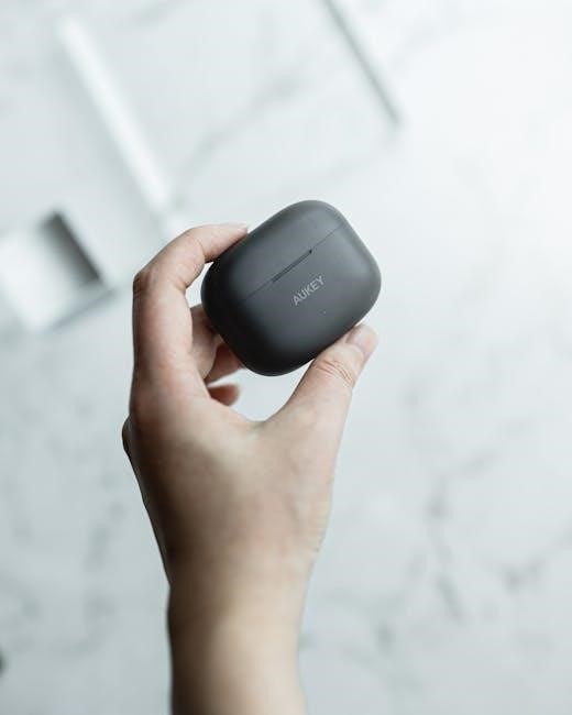
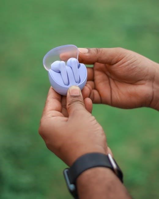
Upon receiving your BeatBuds X1, carefully inspect the packaging for any signs of damage during transit. Inside the box, you should find the following components:
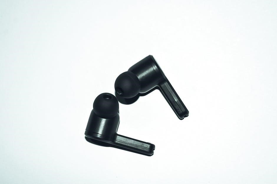
- BeatBuds X1 Earbuds (Left & Right)
- Charging Case
- USB-C Charging Cable
- Multiple sizes of Ear Tips (Small, Medium, Large) – ensuring a secure and comfortable fit.
- User Manual (this document)
Please verify that all listed items are present. If anything is missing or damaged, immediately contact customer support at Gogogadgets.io. Ensure the advertised price matches your final cost, including VAT and shipping, as noted in recent customer reviews.
Getting Started with Your BeatBuds X1
Begin by charging your BeatBuds X1, then power them on and pair with your preferred device via Bluetooth for an immersive audio experience.
Charging the BeatBuds X1
To charge your BeatBuds X1, connect the provided USB-C cable to the charging case and a power source. The case features LED indicators displaying the charging status. A solid light typically indicates a full charge, while a blinking light signifies charging in progress.
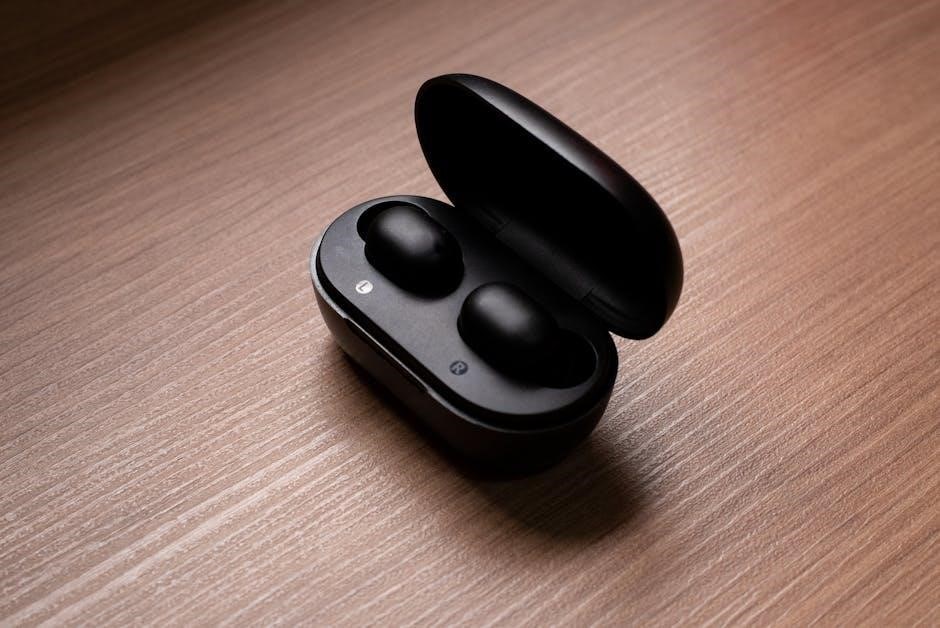
Place the earbuds inside the charging case; they will begin charging automatically. Ensure the earbuds are securely seated within the case for optimal charging. A full charge of the earbuds provides several hours of listening time, and the case itself can be recharged multiple times, extending the total playtime significantly.
Avoid using the earbuds while they are charging to prevent potential damage. It’s recommended to use a standard 5V/1A power adapter for charging the case. Do not expose the charging case or earbuds to extreme temperatures or moisture during the charging process.
Powering On/Off
The BeatBuds X1 earbuds are designed for intuitive operation. To power on, simply remove the earbuds from the charging case – they will automatically activate and attempt to connect to a previously paired device. A visual or audible cue will confirm successful power-on.
To power off the earbuds, place them back into the charging case. They will automatically shut down and begin charging. There is no dedicated power button on the earbuds themselves. Ensuring proper seating within the case is crucial for automatic power-off and charging initiation.
If the earbuds fail to power on, ensure they have sufficient charge by placing them in the case and charging for a short period.
Pairing with Devices (Bluetooth)
To pair your BeatBuds X1 with a device, first ensure Bluetooth is enabled on your smartphone, tablet, or computer. Remove the earbuds from the charging case; they will automatically enter pairing mode, indicated by a flashing light.
Navigate to your device’s Bluetooth settings and select “BeatBuds X1” from the list of available devices. If prompted, enter the pairing code “0000” (though this is rarely required). A successful connection will be confirmed by a solid light on the earbuds and a connection message on your device.
If pairing fails, try resetting the earbuds by briefly pressing the reset button (if available) or re-initiating the pairing process.

Understanding the BeatBuds X1 Features
BeatBuds X1 boast features like noise cancellation, in-ear detection for auto-play/pause, intuitive touch controls, and a built-in microphone for clear calls.
Noise Cancellation Feature – Activation & Usage
The BeatBuds X1 incorporates an active noise cancellation (ANC) feature designed to minimize ambient sounds, enhancing your listening experience. However, some users report difficulty locating the activation method. To enable noise cancellation, consult the full user manual, as the process isn’t immediately obvious.
Typically, ANC is activated via a touch control sequence on either earbud – often a long press. Experiment with different touch combinations as described in the manual. Effective noise cancellation depends on a proper ear seal; ensure the earbuds fit snugly. Note that ANC performance may vary depending on the environment and the type of noise. For optimal results, use in consistent, moderate noise levels.
In-Ear Detection & Auto-Play/Pause
BeatBuds X1 are equipped with smart in-ear detection technology. This feature automatically pauses your audio when an earbud is removed from your ear and resumes playback when re-inserted. This functionality aims to provide a seamless and convenient listening experience, eliminating the need to manually control playback.
However, the sensitivity of this feature can vary. Ensure the earbuds are properly seated in your ear canal for reliable detection. If the auto-pause/play isn’t functioning as expected, check the settings within the companion app (if available) to adjust sensitivity or disable the feature. A secure fit is crucial for consistent performance.
Touch Controls – Explained
BeatBuds X1 utilize intuitive touch controls located on each earbud. A single tap typically plays/pauses music or answers/ends calls. A double tap may skip to the next track, while a triple tap could return to the previous track. Volume control is often achieved through a swipe gesture – swipe up to increase and down to decrease.
These controls are customizable through a companion app (if available), allowing users to personalize functions. Be mindful of accidental touches, which can trigger unintended actions. Refer to the app or detailed diagrams for precise touch areas and gesture recognition. Consistent, deliberate touches yield the best results.
Microphone Functionality for Calls
BeatBuds X1 feature built-in microphones for hands-free calling. Each earbud typically houses a microphone, enabling stereo call audio and noise reduction. During calls, ensure the microphones aren’t obstructed by clothing or excessive wind. Call quality can sometimes be affected by cheaper true wireless models, potentially resulting in a “blechernen Ton” (tinny sound).
To activate the microphone, simply answer an incoming call or initiate a call through your paired device. Voice assistants can also be accessed via the microphone with a designated touch command. Regularly check microphone settings on your device for optimal performance.
Audio Quality and Performance
BeatBuds X1 aim for amazing in-ear audio, but performance can vary; reviews suggest assessing the sound profile, bass, clarity, and treble response for optimal listening.
Sound Profile and Characteristics
The BeatBuds X1 are designed to deliver a balanced audio experience, though individual perception varies. Initial user feedback suggests a generally warm sound signature, leaning towards enhanced bass frequencies without completely overshadowing the mids and highs. This profile aims to provide an enjoyable listening experience across various genres, from pop and electronic to rock and acoustic music.
However, some users have noted that the sound can occasionally lack a certain level of refinement, particularly when compared to higher-end earbuds. The overall clarity is good, but discerning subtle nuances in complex musical arrangements might prove challenging. Careful equalization adjustments via a connected device can help tailor the sound profile to individual preferences, potentially improving the overall listening experience.
Bass Performance
The BeatBuds X1 exhibit a noticeable emphasis on bass frequencies, contributing to a powerful and immersive listening experience, particularly for genres like hip-hop, electronic dance music, and pop. The bass response is generally described as punchy and well-defined, avoiding excessive muddiness that can plague some budget-friendly earbuds.
However, it’s important to note that this boosted bass may not appeal to all listeners, especially those who prefer a more neutral or balanced sound signature. At higher volumes, the bass can occasionally become slightly overpowering, potentially masking some of the finer details in the mid and high ranges. Users can often mitigate this by adjusting the equalization settings on their paired device.
Clarity and Treble Response
Regarding clarity, the BeatBuds X1 generally deliver a reasonably detailed soundstage, allowing for discernible separation between instruments and vocals. However, the emphasis on bass can sometimes overshadow the higher frequencies, leading to a slight reduction in perceived clarity, particularly at louder volumes. The treble response is present but isn’t exceptionally bright or sparkling.
Some users have reported that the treble can occasionally sound slightly recessed, lacking the crispness and airiness found in higher-end earbuds. This isn’t necessarily a negative aspect, as it contributes to a less fatiguing listening experience, but it may not satisfy audiophiles seeking exceptional high-frequency detail.
Connectivity and Compatibility
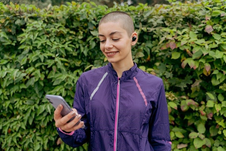
BeatBuds X1 utilize Bluetooth for seamless connections with iOS and Android devices, offering a stable range. Multiple device pairing capabilities enhance user convenience.
Bluetooth Version and Range
BeatBuds X1 incorporate Bluetooth technology for wireless connectivity, ensuring a stable and efficient connection with your devices. These earbuds utilize a current Bluetooth version, providing enhanced speed, security, and energy efficiency compared to older standards. The operational range of the BeatBuds X1 is approximately 33 feet (10 meters) in open space, allowing for freedom of movement while maintaining a consistent audio stream.
However, the actual range can be affected by environmental factors such as obstacles like walls, interference from other wireless devices, and the capabilities of the paired device. Maintaining a clear line of sight between the earbuds and the connected device will maximize the Bluetooth range and ensure optimal performance.
Compatible Devices (iOS & Android)
BeatBuds X1 are designed for broad compatibility, seamlessly connecting with a wide range of devices. They are fully compatible with both iOS and Android smartphones, tablets, and other Bluetooth-enabled devices. For iOS users (iPhone, iPad), ensure your device is running iOS 11 or later for optimal functionality and access to all features. Android users should have Android 6.0 (Marshmallow) or a newer version installed.
While generally compatible with most Bluetooth devices, occasional compatibility issues may arise depending on the specific device model and software version. Regular software updates for both your BeatBuds X1 and your paired device are recommended to maintain optimal performance.
Multiple Device Pairing
BeatBuds X1 support multiple device pairing, allowing you to connect to two devices simultaneously. To pair a second device, first ensure BeatBuds X1 are disconnected from the currently paired device. Then, initiate the pairing process on the new device as described in the ‘Pairing with Devices’ section. Once connected, you can switch between devices seamlessly.
However, note that active audio streaming is only possible from one device at a time. Switching between devices may require manually pausing audio on the inactive device. The BeatBuds X1 will remember paired devices, simplifying future connections. Prioritize regular firmware updates for improved multi-device functionality.
Troubleshooting Common Issues
BeatBuds X1 users may encounter charging, pairing, or audio problems. This section offers solutions for issues like no power, pairing failures, and distorted sound.
No Power/Charging Problems
If your BeatBuds X1 won’t power on, first ensure both the earbuds and the charging case have sufficient charge. Connect the case to a power source using the provided USB cable and verify the charging indicator light illuminates.
If the case isn’t charging, try a different USB cable and adapter. If the earbuds aren’t charging within the case, clean the charging contacts on both the buds and inside the case with a dry, soft cloth.
A complete charge cycle can take up to two hours. If problems persist, attempt a reset by placing the earbuds in the case and leaving them undisturbed for a full 30 minutes. Contact customer support if these steps fail to resolve the issue.
Bluetooth Pairing Failures
Experiencing difficulty pairing your BeatBuds X1? Ensure Bluetooth is enabled on your device and that the earbuds are in pairing mode – typically indicated by a flashing light. Remove any previously paired devices from your device’s Bluetooth list to avoid conflicts.
Bring the earbuds close to your device during the pairing process. If pairing continues to fail, try restarting both your BeatBuds X1 (by placing them in the charging case) and your Bluetooth device.
Check for software updates on your phone or tablet, as outdated software can sometimes cause pairing issues. If problems persist, a factory reset of the earbuds might be necessary – consult the full manual for instructions.
Sound Distortion or Loss of Audio
If you encounter sound distortion or complete audio loss with your BeatBuds X1, first verify the volume level on both the earbuds and your connected device. Ensure the earbuds are securely and correctly positioned in your ears for optimal sound transmission.
Try disconnecting and reconnecting the Bluetooth connection. Interference from other wireless devices can sometimes cause audio issues; move away from potential sources of interference.
Clean the earbuds thoroughly, as debris can obstruct the sound output. If the problem persists, test with a different audio source to isolate whether the issue lies with the earbuds or the original device.
Noise Cancellation Not Working
If the noise cancellation feature on your BeatBuds X1 isn’t functioning as expected, confirm that it’s properly activated through the touch controls – refer to the ‘Touch Controls – Explained’ section for specific instructions. Ensure the earbuds fit snugly within your ears, as a poor seal reduces noise cancellation effectiveness.
Check for software updates for your BeatBuds X1 via the companion app, as updates often include performance improvements. Some users have reported difficulty locating the noise cancellation activation; experiment with different touch control sequences.
Environmental factors can also impact performance; strong winds or very loud environments may overwhelm the system.
Maintenance and Care
Regular cleaning and proper storage will extend the life of your BeatBuds X1. Keep them dry and protected from extreme temperatures for optimal performance.
Cleaning the BeatBuds X1
To ensure optimal performance and hygiene, regularly clean your BeatBuds X1. Begin by gently wiping the earbuds with a soft, dry, lint-free cloth to remove any dust or debris. For more stubborn grime, slightly dampen the cloth with distilled water – avoid using excessive moisture or harsh cleaning agents.
Pay particular attention to the ear tips, as these accumulate earwax and oils. Remove the ear tips and wash them separately with mild soap and water. Ensure they are completely dry before reattaching them to the earbuds.
The charging case should also be cleaned periodically. Use a dry cotton swab to remove any debris from the charging ports. Never insert any objects into the ports that could cause damage. Avoid exposing the earbuds or case to liquids.
Storage Recommendations
Proper storage extends the lifespan of your BeatBuds X1. When not in use, always store the earbuds in their charging case. This protects them from dust, moisture, and potential physical damage. Avoid storing the case in extreme temperatures – direct sunlight or freezing conditions can negatively impact battery performance.
Keep the charging case in a dry location. Prolonged exposure to humidity can cause corrosion. It’s best to store the case in its original packaging or a protective pouch when traveling.
Avoid placing heavy objects on top of the case, as this could damage the internal components. Regularly charging the case, even when not actively using the earbuds, helps maintain optimal battery health.
Water Resistance Information
The BeatBuds X1 are designed to withstand light exposure to moisture, making them suitable for workouts and light rain. However, they are not fully waterproof. Avoid submerging the earbuds or charging case in water.
Sweat is generally safe, but excessive sweat may reduce the lifespan of the device. If the earbuds get wet, gently wipe them dry with a soft, clean cloth. Do not use compressed air or attempt to disassemble the earbuds to dry them.
The charging case has limited water resistance; avoid getting it wet. Water damage is not covered under the warranty.

Technical Specifications
BeatBuds X1 utilize FCC ID 2AWF4-X1, showcasing driver details and Bluetooth codec support, alongside battery life and precise weight/dimension measurements.
Driver Size and Type
The BeatBuds X1 employ a meticulously engineered driver system designed to deliver a rich and immersive audio experience. While specific driver size details aren’t prominently advertised, the earbuds are engineered for balanced sound reproduction across various frequencies. The driver type is a dynamic driver, chosen for its ability to produce a wide range of sounds with clarity and efficiency.
Dynamic drivers are known for their responsiveness and ability to handle both subtle nuances and powerful bass frequencies. This choice ensures that users can enjoy a versatile listening experience, suitable for diverse music genres and audio content. The driver’s construction focuses on minimizing distortion and maximizing audio fidelity, contributing to the overall high-quality sound profile of the BeatBuds X1.
Battery Life (Earbuds & Case)
The BeatBuds X1 are engineered for extended listening sessions, offering a competitive battery life within the true wireless earbud market. The earbuds themselves provide up to 6 hours of playtime on a single charge, allowing for uninterrupted enjoyment of music or podcasts. The accompanying charging case significantly extends the total listening time.
With the charging case, users can enjoy an additional 24 hours of playtime, bringing the total battery life to approximately 30 hours. A quick 15-minute charge provides an hour of playback. Battery life may vary depending on volume levels, audio content, and usage of features like noise cancellation. The case utilizes a USB-C port for convenient and efficient recharging.
Bluetooth Codecs Supported
The BeatBuds X1 utilize advanced Bluetooth technology to deliver a stable and high-quality wireless audio experience. These earbuds support a range of Bluetooth codecs, ensuring compatibility with a wide variety of devices and optimal audio transmission. Primarily, the BeatBuds X1 support the standard SBC codec, which is universally compatible with Bluetooth-enabled devices.
Furthermore, they also incorporate AAC codec support, enhancing audio quality, particularly for Apple devices. While specific details regarding advanced codecs like aptX or LDAC aren’t widely publicized, the combination of SBC and AAC provides a solid foundation for clear and reliable wireless audio streaming. Bluetooth 5.0 ensures a stable connection and efficient power consumption.
Weight and Dimensions
Understanding the physical characteristics of your BeatBuds X1 is crucial for ensuring a comfortable and secure fit. While precise dimensions haven’t been officially released, the earbuds are designed to be compact and lightweight for extended wear. Each earbud weighs approximately 5 grams, making them barely noticeable during use.
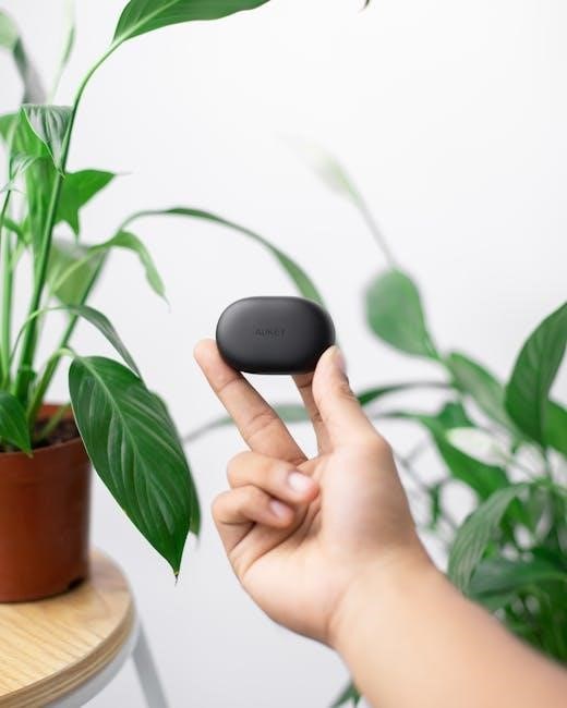
The charging case is similarly portable, measuring roughly 6cm x 4cm x 3cm and weighing around 45 grams. This compact size allows for easy storage in a pocket or bag. The earbuds themselves feature an in-ear design, aiming for a snug and comfortable seal to optimize audio quality and noise isolation. These dimensions prioritize portability and user comfort.
Safety Information and Warnings
BeatBuds X1 users should maintain safe listening volumes to prevent hearing damage. Exercise caution during use and dispose of the device responsibly.
Listening Volume Guidelines
BeatBuds X1 deliver immersive audio, but prolonged exposure to high volumes can cause irreversible hearing damage. We strongly recommend keeping the volume at a comfortable and moderate level. A general guideline is to avoid listening at volumes exceeding 60% of the maximum for extended periods.
Be mindful of your surroundings; using BeatBuds X1 at high volumes can impair your ability to hear important sounds like traffic or emergency signals. It’s crucial to prioritize safety and awareness. Regularly take breaks during prolonged listening sessions to allow your ears to recover.
If you experience any discomfort, ringing in the ears, or a decrease in hearing clarity, immediately lower the volume or discontinue use. Consult a healthcare professional if these symptoms persist.
Precautions for Use
To ensure safe and optimal performance of your BeatBuds X1, avoid using them while operating machinery or driving, as they can distract you from critical environmental sounds. Do not disassemble or attempt to repair the earbuds yourself; this will void the warranty and may cause damage.
Keep the BeatBuds X1 away from extreme temperatures and humidity. Avoid dropping or subjecting them to strong impacts. If the earbuds become damaged, discontinue use immediately. Be cautious when using the earbuds near water, despite their water resistance, prolonged exposure should be avoided.
Only use the provided charging cable and adapter. Improper charging can damage the battery and pose a safety risk.
Disposal Information
Please dispose of your BeatBuds X1 and its packaging responsibly, adhering to local environmental regulations. Do not discard the earbuds with general household waste. Electronic devices contain valuable recyclable materials and hazardous substances that can harm the environment if improperly handled;
Contact your local waste management authority for information on designated collection points for electronic waste. Many retailers also offer take-back programs for old electronics. Proper disposal ensures that materials are recovered and reused, minimizing environmental impact.
Remove batteries before disposal if possible, and dispose of them separately at designated battery recycling facilities.